The Pandalon has been sitting for a while, as I've been absorbed in other projects and activities, but as usual, the delay has been productive: things have been "simmering" in the back of my mind, and I think I have some ideas on how to do various things better than I was planning before.
Most significantly, I think I am not going to attempt to build this complex two-stage, single-pedal, machine pedal system. Instead, as originally planned, I will use the simpler method of controlling each of the two machine rails with a separate pedal. So there will be three pedals total: machine-1, machine-2, and sustain. And three bicycle cables, instead of two, but they are cheap and readily-available. With the two machine pedals, it'll still be possible to get all the effects of the single two-stage pedal, plus of course more flexibility. Since some of the stops are "buzzy" or harmonics-adding, and some are muffling in nature, there will be a general tendency to have two separate types of effect that may be wanted, two axes of sonic change which may not benefit by being forced onto the same continuum. In any case, once the system is fitted for three pedals, it'll be easy enough to add the two-stage behaviour as an option, through modifications only to the pedal unit itself.
So that's all the explanation for why it "doesn't hurt" to go back to double machine pedals, but the actual *reason* is that the forces and frictions, at least the way my current stops action is designed, will work out much better this way. The two-stage mechanism requires another layer of friction and spring force on top of the two "pulls" themselves. The pulls already have tons of force, but I think they will operate smoothly and with a good feel, once directly connected to pedals with the right leverage. I was having doubts about how clunky and noisy and possibly even squeaky the two-stage mechanism might be. I had re-designed it several different ways, but nothing was quite sitting right about it, in my head.
The critical thing here is to have pedals which can be operated quickly and easily, without undue noise and without too "indirect" of a feel, even though the mechanism is totally indirect. My model for the kind of pedal-use I want to support, is the virtuoso hammer-dulcimer players of the Eastern Block: they often have a damper pedal, which operates a simple pull-down damper on all the strings (i.e., normally-undamped). They use this damper very quickly to accent and mute different parts of phrases, and there also seems to be a considerable linear range to the response of the damper, so they are able to obtain a range of tone colour from light damping (a change in harmonics but still with sustain) to very percussive highly-damped "plunks". I want my buff stop to be able to do all of this, so that it can be used in exactly the same way. I think the double pedals will enable this much more readily.
Tuesday, December 2, 2014
Saturday, August 30, 2014
springs
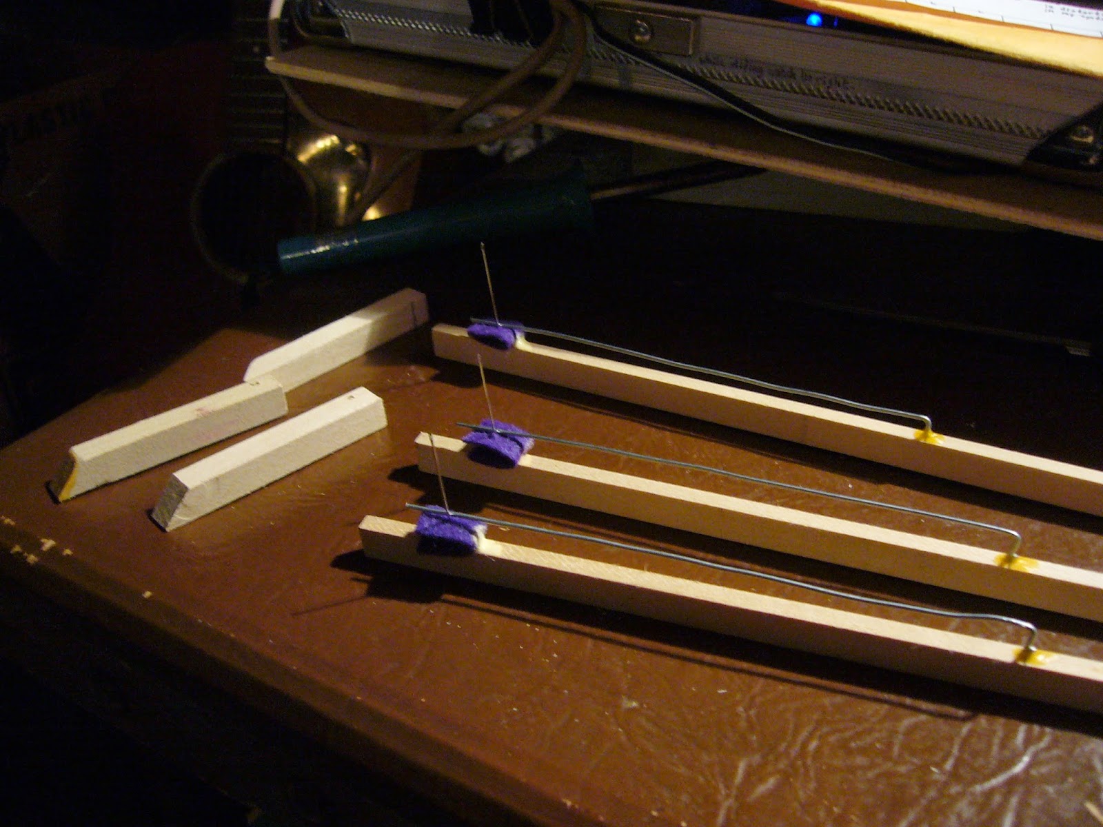
After a number of attempts (resulting in a sizable "graveyard" of scraggly wire bits), I think I finally have the springs working, for the machine-pedal aspect of the stops mechanism. It was difficult to find the right strength for the springs, to overcome the considerable (intentional) friction in the stops motions, without presenting so much force as to make pedal operation unpleasant -- or simply, so much force that my simple wooden mechanism would self-destruct. And, it was difficult to fit the necessary springs into the cramped and irregular volume of space available for this part of the mechanism. Here, then, is what I came up with...
First, I made models using thinner wire (#18 steel). This is a crucial point; trying to work and re-work an already crooked and kinked-up piece of #12 steel wire, to snake around all the obstacles and fit into the right place, was an exercise in frustration which I repeated several times in previous attempts (I have already mentioned the "graveyard"). Once I realized I needed to fit a *pair* of springs into the same space, for each of the four ends of rails which needs a spring, I knew I had to get serious with the modeling.

Here are two of the four final pieces, in #12 steel wire. You can see that I have marked left and right (one or two bands), because they are not interchangeable. They're *roughly* mirror images, but each is shaped to fit into its exact situation.

Here you can see how the pairs of springs interlace, in-vitro.


You can see how limited the clearance is, between the nameboard and the wrestplank (it's about 3"). I've had to substantially refine the design to fit into such a space: the original idea would have required more like 12" of clearance behind the panel (so it obviously would have had to be placed in a very different way on the instrument, not on the nameboard).

Monday, August 4, 2014
various refinements to stops mechanism; major redesign of damper system


The other change, to not-yet-implemented aspects, is that I have decided to put 2:1 levers in between the machine rails and the sliding trapwork with the inclined plane, which moves with the pedal. The force on the rails will be quite large, and therefore very strong return springs will be needed. Some mechanical advantage from the levers will help the sliding planes, which I call the "hills", do their job more smoothly.
Meanwhile, I've benefitted from this long break in working on the keyboard action itself. As often happens, my mind churned over a problem that was bothering me, and somehow it arrived at a solution "in the background", as my conscious focus was on other things (the stops). The problem was, too much friction in the damper system (with the springs and monofilament going over "pulleys"): I had assumed that monofilament making a close 90-degree bend over a smooth metal surface, was close to frictionless, but far from it. I could possibly have mitigated the issue by using actual, moving pulleys, but then things just got 98 pulleys more complicated, where I thought a straight piece of wire was going to do. And, 98 pulleys of unknown design, from an unknown source. Me, fabricate? All this bothered me.
But then I realized a better solution, going back to something I had discarded before, is to use levers. There is not room for damper levers above the keylevers, as in some early designs of mine; but there is room below. The change works out to be smoother than one might think. Same damper guides in the upper touch rail. Same monofilament adjustment screws in the tops of the keylevers. But instead of springs and pulleys, the monofilament directly lifts up the front end of the damper lever. The back end goes down, by a smaller amount (about 2:1), taking the damper wire down with it. The weight imbalance of the asymmetrical lever is, hopefully, enough to return the mechanism by itself, without added weights.
Not only is this likely to move with less friction felt at the keyboard, but also it provides a nice low-force way to implement "sustain", by lifting the front ends of all 49 levers at once. I have been worried that the force on the stops mechanism from pulling down 49 damper springs, was going to be too much and would make the machine pedal interface unworkable. There are still many worries there, but this big issue is at least significantly mitigated with these gravity-levers.
Friday, July 25, 2014
starting on the stops mechanism

The one slightly non-trivial part was making the slots in the machine-rails; these are of poplar. I was able to "drill-route" them using a sharp drill bit on the drill press, by drilling holes with diameters that intersect, then grinding away the rough sides that remain using the same drill bit, carefully working until a channel is produced that the drill can slide freely through from end to end. Results look quite crude and home-made, but functionally it works fine, and perhaps the rough sides give a better grip on the screw eyes or something. (These rails could also have been built out of strips and blocks glued together, like the way some harpsichord registers are made, if one wanted to avoid my non-Kosher sideways drill use and still do it with minimal tools.)

Guides for the rails, and several other structural supports, are glued to the back of the nameboard, which forms the basic chassis for this whole mechanism. The guides, 1/4" dowels, are glued into shallow drilled holes. The rest of the blocks are simply glued to the surface. Although I tried to mask-out some areas where I thought I'd be gluing, turns out in every case I had to sand and scrape away paint and finish to place each new block as I went, and the masked areas never got used. Oh well! (This is the cost of pre-finishing parts as early as possible, on an evolving prototype design, rather than delaying finishing as long as possible.)

The stop knobs have to be threaded through first, and their screw-eyes installed, ahead of everything else, or else they can't be reached conveniently.


The rails slide into place over their guide-dowels...

When a stop knob is turned to the left or right, its screw-eye engages a slot on one of the rails. The rails are moved by the machine pedal. When the stop knob is pointing straight up, its screw-eye misses both rails, and thus the stop is in "manual" mode.

The backing plywood, and all the additional parts of the mechanism, are held with sheetrock screws, so everything can be disassembled at will.

The stops knobs were initially hanging down in a position past their normal full-out travel position, with the screw-eyes resting against the nameboard. Here I have pushed them in slightly and turned them to engage with one of the machine rails, which are themselves resting in the full-out position with gravity. Thus, the back ends of the stops dowels are now visible at the surface of the plywood guide holes, in their correct full-forward position (where I can reach them to attach the lower portions).

The lower dowel portions, I don't have a good technical name for. The upper dowel turns with the knob, this part is rotationally stationary but it slides in and out with the knob. Anyway, this portion, each one I have drilled with four holes so that the order of the stops can be re-arranged. (Although I have already chosen the actual order of the knobs, now determined by the names painted on the nameboard, the ordering of some of the back-end mechanism may still change.)


The spring-force of the wire actuator arms on the rollers, along with the springiness of the thin 1/4" dowels themselves, gives each stop a gentle but positive "click" action, where it wants to be fully-drawn or fully-pushed-in, but not somewhere in the middle.

Here the four left stops are pushed in...

...Here they are pulled out. The rollers turn through a small angle, which will be translated to pull-force by wooden arms at the outside ends of the rollers (not constructed yet). The length of the arm will determine leverage of course; in most cases, the motion will be reduced 1/2x or 1/4x from the knob travel (which is about 1/2").


Here I've added the brackets which carry dowels for the machine-pedal carriage mechanism, not yet constructed. The dowels slide back and forth with the motion of the pedal (transferred by bicycle cable). Elements attached to the dowels carry inclined planes (the "carriage"), which along with rollers cause the rails to be pushed forward in sequence at the proper point in the pedal travel: first the top rail, then it is joined by the bottom rail. Strong spring force pulls back the rails, and also the pedal carriage.


Here you can see that I have used the re-arrangeability of the rollers, to put stop #8 on the back roller, out of the sequence followed by the other seven stops. The 8th stop is "sust", and it needs to reach downwards to control the damper-lift, which is more convenient to do from the back roller; most of the other stops will pull cords or levers to the back and above their corresponding rollers.


With all the knobs turned to the right, all stops are engaged with the lower rail. Here, they are all in the pushed-in position...

...When I manually push the lower rail forward, all the stops move forward to the drawn position. The difference is highlighted by the unpainted-but-finished section of the dowels, which becomes visible. I may paint this region red, or something.

Monday, June 16, 2014
nameboard and stops design

Well, now it's official, I have to finish this instrument by the end of this year!
As you can see, I have started fabricating the front panel (nameboard) and other elements related to the stops mechanism. In order to do the lettering, I had to finally decide on the order of the stops:
8va sitar bsoon buff mod mute1 mute2 sust...which is somewhat determined by the mechanical constraints, but turns out to be a good ordering from a functional point of view as well. This gives something of a tonal continuum, left to right, from "buzzy" to "muffled". Also, all of the stops which modify the tone after initial excitation, i.e., the "mutation" stops, are to the left. On the right side are the controls which do other things than tone mutation: the moderator affects the initial production of tone, the mutes bring on silence. Originally I had planned to make these mute stops "pull for sound", but now they will instead be "pull for silence". This is mainly to make them work in a more-useful manner with the machine pedal (the left pedal): as the pedal is pushed down, adding sonic effects (which, generally-speaking, tend to reduce the total volume of sound), it is more likely that one will want to remove an active string from the pair, rather than add one. Especially given that some of the effects (sitar, 8va) only affect one of the two strings in a pair: the first pedal position (part-way down) can introduce the effect while leaving both strings active, and then the second pedal position (all the way down) can mute the other string which doesn't have the effect, thus causing the effect to become much more prominent.
The stops mechanism will be attached to the back of the nameboard, fitting into the 4 inch space between the nameboard and the front of the wrestplank (usually nameboards are mounted right up against the wrestplank). The entire assembly will be held in place with two screws, not glue, so that it can be easily removed, analogous to the keyboard and action.
Pulling the knobs will activate organ-type rollers which transfer the motion to the sides (four to the left, four to the right), where attached actuator arms will pull control wires forward through a distance of about 1/2" (3:1 leverage from the knobs). Each stop mechanism will have a low-force spring return (low enough force as to not override the stronger spring-induced "click" which seats the stop knob into either the fully-pushed-in or the fully-pulled-out position.
The stop knobs can be rotated as well as pulled. When the knob is pointing straight up, in the vertical position, the stop is in manual mode, and it can be pushed or pulled freely. Turning the knob to the left engages the stop with pedal position 1, and to the right engages with position 2. When stops are engaged to the pedal, they can no longer be moved by hand; instead, as the pedal is pushed down, first all the stops engaged to position 1 are moved outwards; as the pedal is pushed further, the stops engaged to position 2 also move outwards. Releasing the pedal retracts the stop knobs, in the corresponding reverse order. (Stops can be disengaged from the pedal, by rotating the knobs back to vertical, at any time, whether the pedal is down or up; the stops stay in whichever state they were in at the time they were disengaged.)
One issue yet to be figured out, is how to manage the spring force inevitably associated with the sustain mechanism (damper-lift). Unlike all the other stops, which don't have an intrinsic spring force and which will have specific return springs added, the sustain stop has a relatively large amount of spring force to act against: it has to push all the damper springs down simultaneously, thus lowering the dampers away from the strings (in my unusual, dampers-from-underneath design). This force is no problem to handle with the leverage of the dedicated sustain pedal (the right pedal). However, in keeping with my gadget-centric design sensibility, I want to also treat the sustain function as "just another stop", susceptible to the handstop and machine-pedal mechanism like all the rest. (Initially I avoided this conclusion, but at the very least I wanted to have a handstop which allows the dampers to be permanently disabled without having to hold the pedal down: this, after all, is the primary mode associated with historical pandalons (more often spelled "pantalons"), as well as with the hammered dulcimer itself, the underlying inspiration for this type of instrument.)
Having the sustain stop susceptible to the machine pedal, would seem to imply that the "click" force of the sustain handstop will have to be strong enough to hold the stop in the out position, against all the damper spring force. I don't yet have a clear vision of how this will work. I suspect the "click" will have to be too strong. Using a mechanism involving an inclined plane which "plateaus" can eliminate the back-pull of the springs when the stop is fully out, but still something will have to provide all the force to move the knob in the first place. Anyway, no clever solution here yet, but I'm seeking one...
Monday, June 9, 2014
keylevers...
I have started fabricating the keylevers and associated parts, which involves much repetition at rates of 49 or multiples thereof.
Unlike in my three-key prototype, on the real keys, I have decided to use little blocks to hold the striker spring wires. On the prototype, these wires made a 90-degree bend and were seated into shallow holes in the keylever itself, but this has proven unsatisfactory: a firmer seating is needed, and I don't like drilling deeply into the already precariously thin and light keylevers.
The blocks have a horizontal hole drilled through, end to end. The spring wire will seat into the back end of this hole, facing the striker. The hole on the front face may be used for an optional "secondary touch" mechanism which I have designed; I won't be sure whether the mechanism is needed until I play the instrument for a while.

I made this little jig to hold the blocks in position for drilling.
I have gradually developed a technique for obtaining reasonably-accurate hole positions, despite the remarkable tendency of small drill bits to wander, and despite what seems like a large amount of play in my drill press bearings (are they all like that, or only the dirt-cheap ones from China?). The key is to have a well-placed starter mark, which I make with an awl; and then I position the drill (with the power off) with its tip centered in the starter mark, and *then* turn on the power. Because I often need one hand to help hold the piece, and the other hand to hold the drill press lever, I installed a wire-tie hanging off the end of the power switch, so that I can pull it with my teeth and thus turn on the power when my hands are occupied. Potentially dangerous, but effective! (Given how much easier it now is for something sweeping past to snag the wire tie and turn on the drill, I'm now much more careful about pulling out the little plastic "ignition key" which disables the switch, when I'm not using it.)

I thought I'd have to rig a complicated and tedious clamping system to glue the blocks onto the keylevers. However, the Titebond II sets up so fast on these dry, porous, absorbent basswood joints, that I found I could just hold the joint firmly by hand for less than a minute, and the parts would already be firmly stuck together. Then I'd just let them sit for an hour or so, and good to go. Indeed, one block I noticed I wanted to move, after only about two minutes of drying, and I just *barely* got the pieces apart in time; it took quite some force to break the bond. Very much longer, and it would have been the wood that was breaking.

Here are the 49 keylevers in the frame. I will next attach the plywood keys (but not their ceramic and glass coverings, yet). Then I will do the painting and finishing I have planned for the levers: black paint on the keys, clearcoat on the rest of the levers. Then I will finally attach the guide-wires, spring-wires, and felt pads for the strikers (thus these items will not be exposed to the clearcoat).

I have found rectangular glass tiles with a white background, which are the perfect shape and surface quality for the sharp keys. However, I'm still searching for the right solution for the natural key coverings. I am convinced that ceramics *may* be a good key covering; but I've been unable to find pre-made tiles which fit the bill, despite many "almosts". So I am now planning to try making my natural keys out of clay, myself -- for the second time. I already tried making the naturals from "Della Robbia" oven-bake clay, but this type of clay will clearly not be durable enough for this application. So now I will try "real" clay, fired in an actual kiln at 2000-something degrees F, with glossy black glaze.
Monday, May 26, 2014
framed for posterity
Done with the basic keyboard frame, which gives a good chance to view it and contemplate its basic design, before I add a whole lot of other parts and mechanisms (such as the dampers) which will tend to obscure the basic simplicity of the striking mechanism.
As you can see here, there are three crucial rails, plus the decorative/protective black front rail. The fulcrum rail has little blocks of wood which support the keylever axle wire, and also it has a "comb" of steel nails, which guide the keylevers (these unusual details, instead of the usual center "balance" pins underneath the keylevers). The lower touch rail, farther back, has the other "comb" of nails, completing the side-to-side guide system for the keylevers. The upper touch rail has no nails, but it has holes drilled through which will guide the damper wires (as seen on my 3-key prototype).

Here the frame is attached to the instrument (which is resting sideways, on its spine edge).

Next up, a whole lotta keylever fabrication, using the lessons I've learned from the prototype...
Tuesday, May 20, 2014
starting on the keyboard frame
I've started constructing the frame for the keyboard and action. It's mainly composed of poplar 1x2s. Everything will be spray-coated with clearcoat, as I'm putting it together.
I added attachment blocks to the instrument, to allow precise positioning: I don't necessarily trust my 2x4 frame to be perfectly straight and square! Also, the blocks enable (I hope) three transposition positions, for 440Hz, 415Hz, and 392Hz. This is simply a matter of attaching the action in three different positions with a set of correctly-spaced holes. But there has to be clearance. 415 will definitely fit, 392 I'm still not sure about...

Whole bunch of hole-drilling, and quite a bit of jigsaw-carving, to make the parts for this. Much more yet to be done, e.g., the keys themselves!

Here I have it assembled. Nothing is glued yet, I'll drill some more holes, and finish and paint several parts, before finally gluing it up.

Here you can see my adjustment mechanism for the upper and lower touch rails: a critical aspect of this action design. This scheme is one of my "inventions", which I have assumed to be viable for years in my notebooks and on-paper designs, but only now am I finally trying it out in real life. Seems to work as I wanted, thankfully.

Yet to be fabricated, are the two rails which go on the bottom, and which I call the pulley rails -- even though the "pulleys" are just shiny metal surfaces with, hopefully, low friction. These rails guide the monofilament control cords which move the dampers when the keys are pressed.
I added attachment blocks to the instrument, to allow precise positioning: I don't necessarily trust my 2x4 frame to be perfectly straight and square! Also, the blocks enable (I hope) three transposition positions, for 440Hz, 415Hz, and 392Hz. This is simply a matter of attaching the action in three different positions with a set of correctly-spaced holes. But there has to be clearance. 415 will definitely fit, 392 I'm still not sure about...
Whole bunch of hole-drilling, and quite a bit of jigsaw-carving, to make the parts for this. Much more yet to be done, e.g., the keys themselves!
Here I have it assembled. Nothing is glued yet, I'll drill some more holes, and finish and paint several parts, before finally gluing it up.
Here you can see my adjustment mechanism for the upper and lower touch rails: a critical aspect of this action design. This scheme is one of my "inventions", which I have assumed to be viable for years in my notebooks and on-paper designs, but only now am I finally trying it out in real life. Seems to work as I wanted, thankfully.
Yet to be fabricated, are the two rails which go on the bottom, and which I call the pulley rails -- even though the "pulleys" are just shiny metal surfaces with, hopefully, low friction. These rails guide the monofilament control cords which move the dampers when the keys are pressed.
Saturday, May 10, 2014
more work on key design
I've mentioned my experiments with arcade-cutters, fashioned as you see below by cutting away pieces from these low-grade steel thumbscrews, and filing-in some interesting notches and steps; the resulting doo-hickey then fits into the drill press to make a rotating cutter. I make a row of such circular cuts on a strip of wood, then slice the strip in two right through the centers of the circles, producing a strip of half-circular arch patterns, which I then dice into the individual blocks.

Here, I am gluing two of the arcade-blocks onto my prototype's two natural keys. Also I'm gluing the glass tile and stacked wooden block onto the sharp key in the middle.
Ultimately, all the wooden parts of the keyboard will be painted black; the naturals will be topped with black ceramic tiles (not the ones I'm using here in the prototype, though); the glass sharp tiles have a white background already, handily enough; and then the arcades (just the curved part) will be hand-painted with metallic gold.

As I have added the mass of the arcades and tiles to the fronts of the keylevers, it has put my key-action all out of whack. With no keys on the fronts, the bare keylevers were working pretty well with a 5:1 fulcrum position. Once the keys were added, the length extension dropped the ratio to as low as 2.5:1, which felt too low. And the mass made the levers too close to balanced: not enough return force. (None of this was a surprise: I was already worried when I found how well the levers worked without the keys; I had hoped they'd be too "hard" and too much leverage, so that adding the keys would "fix" the problem.)
So I've gone from being afraid of too much leverage, to wondering how I can get enough! Basically, the fulcrum wants to be just about right up at the back end of the visible key surfaces, i.e., right underneath the name-board of the instrument. This means that there will be a large differential in "touch" between the front and the back of the keys -- indeed, the backs of the sharps will likely be pretty much unusable. And the keys will have a noticeable curved trajectory, there won't be any illusion of pushing straight down on something. Essentially, the playing position will tend to be right out on the front edges of the naturals and sharps. And the dimensions of these keys are much shorter than modern piano keys, which will facilitate this type of playing. Short strokes, with curved fingers: I believe the style will be more similar to what is called Baroque fingering style, though I am no expert on any kind of fingering style.
So I will have to re-juggle the elements of the front guide, to put the fulcrum far forward and the first set of guide nails behind. Also, I think I will have to change the position of the damper-cords, i.e., the position of the hole which determines where their pulling force is taken from the lever. In the prototype I started out with a very short distance from the fulcrum, even less than 1:1 motion ratio. I like having the dampers move slowly and only a small amount, but it needs to be a little more because I find I want to adjust the travel of the keys down to a narrow, high-leverage stroke. The dampers were working well with the original, longer key-dip, but I think once I have both lower and upper touch rails adjustable (lower is fixed on the prototype) I will want to dial the stroke down and this will make the damper motion too slight.
I hope that once the fulcrum is moved forward, there will be enough or close-to-enough returning force. But I suspect more will be needed. So the question is, how to obtain it? A second set of springs would work, as I plan to use on the clavicytherium, and then the action would be fully adjustable in every important respect. But I don't like the idea of making things intentionally "more difficult", for no gain. Another possibility is to increase the mass of the strikers, either by adding metal (small washers and screws perhaps), or by using larger/heavier pieces of wood. Mass added to that end has a 5x amplification. And there does not seem to be any problem yet with the strikers being too massive (e.g., second-bounce). Greater mass will presumably increase the maximum forte loudness available (though I still don't think I understand even the basics of percussive sound production very well). More interestingly, I believe greater mass will enable a lighter touch for piano: a slower minimum velocity will still cause the mass to move far enough to touch the string. So it seems like, perhaps I should increase striker mass until either mass-related problems start to appear, or until I obtain enough return-force; and springs or weights on the lever which are not part of the striker, should only be used to fill in if a limit is hit in striker mass.
Saturday, May 3, 2014
dampers added to prototype

Here is the complete 3-key prototype, showing the articulation dampers.
The keyboard would be on the left side in this picture. As a key is pressed down and the long end of the keylever lifts up, the nylon monofilament cords controlling the damper are pulled upward, but only a short distance because the cord attachment point is close to the fulcrum (just behind the adjustment screws). This upward tug on the pair of cords is transferred via the two "pulleys", to a downward pull near the end of the damper spring. The springs are straight horizontal wires, #18 steel, which pass through felt-insulated holes in the thicker (#16) vertical damper wires. The damper wires are guided by holes running through the upper touch rail; so when the spring is pulled down, the felted top of the damper moves down, allowing the strings to vibrate freely as long as the key is held down. When the key is released, the damper felt is pushed up against the strings, with the force of the damper spring (which is adjustable). In the real action, there will also be a sustain mechanism, operated by pedal or handstop, which presses all the damper springs down at once, thus eliminating articulation and producing that harplike, reverberant open sustain sound -- a sound which is unavailable with harpsichords and many other early keyboard instruments.
In the prototype, I have used plain finish nails as the "pulleys"; in the real action, there will be wooden rails with holes drilled which the monofilament will pass through, before making a right-angle turn around a length of round-section brass rod (there still won't be any moving wheels in these "pulleys"). The guide-holes in the wooden rails are needed, because when the sustain pedal is activated, all the cords go slack and they tend to wander sideways out of their proper lines of operation, even crossing over their neighbors on the prototype where there is nothing to prevent that. Slots cut from the edge of the rails into each guide-hole will allow the loop of
I am glad I took the time to build this prototype, I have found several things that I need to change or alter before building the real action. There is no problem with the "5:1" ratio, it is not too high; indeed, when the keys are glued to the ends of the levers, the actual ratio at the playing point is significantly reduced, down to as low as 2.5:1. So, I am planning to shift the fulcrum even closer to the keyboard end of the keylevers, so that a ratio closer to a real 5:1 can be obtained, from a reachable place on the keys.
The dampers do add noticeable friction and drag, more than I'd hoped. The adjustable force is always a tease! You can adjust it only so far down: just about the time that it starts feeling pleasingly light in touch, there is no longer quite enough force to reliably seat the dampers, and they start to lag and stick in their guides. To get clean, fast operation, you have to accept a firmer spring force. Hopefully the brass rail in the real action will have lower friction...
A different approach would be to make the dampers come-from-above in the more conventional way. Then they could just use gravity, no springs. However, the obvious way to drive them would be to let the keylever itself lift the damper directly; but this would mean the dampers were flung upwards at the 5:1 amplified velocity of the strikers; and the weight of the dampers would similarly be multiplied by 5, in terms of additional weight to the keyboard feel. So, without actually trying it, I have judged that this approach would probably not work so well in this design. But if the current way turns out to bother me too much, I may try alternatives like this. Another, hybrid approach would be to use come-from-above gravity dampers, but still use the pulleys and cords to give closer to 1:1 motion (lifting the dampers up instead of pulling them down). This almost becomes a thought-experiment to demonstrate that there couldn't be that much benefit over the springs, however: enough weight would have to be added to make the dampers work reliably, and basically all the same sources of friction would still be present.
Oh well, I am pretty happy with the initial results, given that this was all invented on paper over months and years, with no guarantee of success. Even without the changes I now plan to make, the action as it stands works quickly and reliably, it has a wide piano-forte dynamic range, and it already feels faster and lighter than any of the pianos *I* ever get to play. I'd say, results are promising so far, and a lot more research and experimentation is called for, in this long-neglected field of alternative percussive keyboard action designs.
Tuesday, April 29, 2014
prototype action parts
Fabricatin' a whole bunch of small wooden parts, in order to build a small set of prototype keys, before I commit to building the full keyboard and action. I have built a smaller action of this type, for my 15-note zither, so this is in some ways my second pass at this kind of mechanism, and I'm using lessons learned already (particularly, I'm using a lot more motion ratio this time, about 5:1, and my keylevers are longer and thinner than those on that first clunky little prototype). But many things are being tried for the first time here.

There are my strikers, square-section basswood. I made four but then ended up only building out three of the keylevers, later on. One of the remaining three strikers, I have "sized" with Titebond II glue on the angled striking surface. I left the other two plain wood. I am planning to, probably, size all of the strikers on the real action; but I want to see what difference it makes, whether perhaps the plain-wood kind will split or wear down much faster. I suppose, if it makes no perceptible difference, then why do the sizing.

Here you can see the 12" keylevers, with the eye-hooks already in place. These will adjust the dampers.

Here I have the strikers sitting in place on three keylevers, but on the fourth you can see the sewing needle which acts as a guide for the strikers. The strikers are drilled with a long vertical hole, about 1.5" long, through the center, for the needle; and then they also have a horizontal hole all the way through from front to back, slightly offset so as not to intersect with the vertical hole. This latter is for the spring wire.

Here you can see the spring wires in place. I'm not sure about the mounting technique here: because the keylevers are such thin, narrow wood (which is good, for lightness of action), I can only drill a very shallow hole in the top for the folded-over end of the spring-wire to seat into. It's a marginal-enough situation that I sealed each one with a dab of Titebond glue, as you can see. Overall, that seems to result in a functional attachment, but it might be more secure (and easier to fabricate the springs, in addition) to have the spring-wires go straight into a short block of wood glued on top of the main keylever, instead of making the 90-degree bend. This is the kind of stuff that building these prototype keys helps me figure out...

Here you can see the front keylever guide, close-up (the keylevers in the background are foreshortened). Each keylever has a hole drilled near its bottom edge (1/16" diam), which the #16 steel wire passes through, forming the pivot point of the lever. Then the keylevers also pass in between the shiny nails (#8d finish nails, 2+1/2", 7/64" holes drilled for them), which guides the keys in a similar fashion to standard keyboards, except that usually, standard keyboards will have center pins instead of guides on the sides like this. The standard way is possibly quieter; this way is much easier to fabricate (especially with these unusual, slender keylevers).
The keylevers also pass through a similar nail-fence guide, the rear guide, about 7 inches farther back from the pivot point. On the prototype, this guide is fixed, but on the real action, it will be able to raise up and down, thus adjusting the bottom travel limit of the keys.

Much more critical than the bottom travel limit, is the top travel limit. On the real action, the limits will be adjusted with screw-threads. For the three-key prototype, I just used a 1/4" dowel, which fits nice and snug in 1/4" drilled holes (one end glued), with enough friction to stay in place, but still can be adjusted pretty easily. This top travel limit is the whole key to my action: the key swings up until it hits the limit and stops suddenly; the striker keeps traveling, lifting off of the key surface and flying upward to collide with the pair of strings, before being returned by the striker-spring. The top limit is adjusted to bring the strikers very close to the strings, without actually touching them, when they are just sitting on the raised keys. Thus, only a light touch on the keys is needed to make them sound at maximal "piano", but they still get out of the way of the strings and don't make buzzing or second-sounding errors.

And here I am gluing on the felt. The upper and lower limits have felt, and also the strikers are seated on felt, on their respective keylevers. Thus everything operates as quietly as possible, and also, critically, the tendency of the striker to rebound after hitting the string, is minimized: which permits closer adjustment of the upper limit and thus more-sensitive "piano" playing.

Here's the whole deal (well, no dampers yet, that's next). Enough to finally actuate the strings in the way that they will be actuated, and thus, I can finally hear her "real voice" in a very definite sense. Exciting!

...Meanwhile, work also continues in parallel, on the software for the "tuning fork", which will let me finally put the thing into good tune and see how well it holds. All I can say so far is, the bottom strings have held their C2 for several months with no apparent trend, although they track humidity up and down. So the basic holding of the tension is successful.
Subscribe to:
Posts (Atom)