Monday, October 28, 2013

perimeter established

So now I have all of the sides glued on.  There are a couple areas that need additional gluing, probably with this hypothetical filler compound of glue and sawdust, which I have yet to try.  And I will have to fashion thin wedges of wood to glue into some voids, where my cut wandered in trimming the frame.  Most concerning is at the wrestplank end of the spine timber.  I hope I can fashion a tight-fitting wedge, glue it into the void next to the wrestplank, while gluing the wrestplank itself into position, and using the clamping to correct some of the outward cupping on the bottom of the spineside case plank: all in the same operation.


Before gluing in the wrestplank, I will drill holes in the nut for the pins (nails), and attach the nut.  And I will drill pilot holes for the tuning pins, with the drill press, so that I can drill the full-size holes with the handheld drill later on; I could probably maneuver the drill press to work on the wrestplank after it's glued into the frame, but I hope to thus avoid doing that.


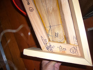
Here, the pieces are just placed in position, in the frame.  You can see my relatively-narrow 2-inch gap, between the wrestplank and the soundboard.  As I am designing the action, I can see it will be tight to fit this spacing.  At this point, I could still choose to make it wider, by fitting spacer blocks when I glue in the wrestplank: ugly, but I think it'd be strong in the right ways.  But, I want to try to target a 2" gap.  This will allow the action to still work with higher notes than I have here, such as instruments with a 4-foot choir (a set of strings 1 octave higher on each note).

The two elements that need space in the gap are the strikers, and the dampers.  The dampers will be vertical wires, passing through holes in a narrow rail, and bent into loops at the top to which felt will be glued.  These come from underneath and press against the strings.  The damper rail will be closest to the soundboard, in the gap.  I'm pretty sure I can build it to occupy less than half of the gap, probably about a third overall, max.

So the strikers will have more than an inch of front-to-back space in the gap, which seems like it ought to be enough.  However, there are complicating factors.  The strikers on this action will necessarily be quite tall, something near 2" (which brings in a host of concerns in itself, as to stability and dynamic behaviour vis a vis the different guide systems in the action -- but presumably I will somehow solve all this and make the strikers work right).  Since the motion of the key is circular, centered on a pivot-point something like 12" away from the striker, the striker moves through a shallow arc, and thus needs more than its own size worth of clearance, towards the front (wrestplank side).  And given the intentional "looseness" of the guide situation, the strikers will need more clearance generally, to ensure no-contact with other elements.  (Unlike other early "tangent pianos" where the strikers moved vertically in harpsichord-like guides, in my action design, the strikers are more or less firmly associated with their keylevers, and follow their motion: the guides for the strikers are attached to the keylevers.)

And the real complicating factor is, the moderator stop.  This is a little strip of cloth, felt, or leather (haven't decided which material yet, will probably have to try them on the real instrument before deciding: just hope I don't decide I want all the types available as separate stops!), which can slide into position between the strikers and the strings, thus softening the tone of the bare-wood strikers.  The effect is as if the strikers themselves were covered with the moderator material.  It's important that the moderator fabric not touch the strings, except when and where a striker has been keyed: when playing with the moderator active, the strings still have their full sustain time, it's just a softer initial excitation; this is in contrast to the "buff" stop, where the strings themselves are muted and have a much-reduced sustain time.

Doing without a full set of tone-modifying gadgets is simply out of the question for me, in-style or not.  So the question is, how can I fit the moderator into all this?  Specifically, where will it "stow" itself, when not in use?  The obvious design for the moderator is a long rail or rod, with the fabric attached along its edge and protruding to one side.  The rail itself does not pass through the path of the strikers, but it moves up close to the strikers, so that the fabric is in their path, or it moves farther away "somewhere", so that the fabric is out of the way of the strikers.  The simple plan would be for the rail to slide horizontally (or move through a wide arc, approximating a horizontal slide), so that when not deployed, the moderator would be taking up its full width of space next to the strikers, in front or in back.  However...  The moderator can't slide to the back, because that's where the dampers are.  (Original pandalons didn't have conventional per-note dampers, so if I were sticking to that exact design concept, I wouldn't have a problem here, but like I said, every possible gadget...  The per-note dampers are particularly important to me: I want to be able to play with articulation, and also to play with the dampers off.  Not many instruments prior to the piano (which has its own problems of course, or I wouldn't be here) gave both options in one instrument, but we don't have to be limited by the past to learn from it.)  And to the front, i.e., between the striker-zone and the nut, will be the rails of two other stops, the buff and the bassoon.  I'm not positive, but I don't think there will be room to park the moderator in the space that remains.  So, I'm considering making the moderator swing through an angle of 90 degrees, and slip down in between the strikers and the dampers, in a vertical orientation.  I think there may be just the right amount of room for the required arc of motion to do this, since the strikers in rest position sit well below the strings.  We'll see, there's plenty of time for me to pull together the exact design of all the stops and gadgets, because I will finish building the full basic instrument first, before I start on these other things.


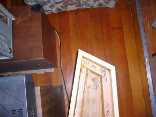
Pretty pointy.  I recently had the opportunity to see if the instrument will likely fit in my friend's car, an early-2000's Toyota wagon.  It will be very convenient if I can fit into this very-typical vehicle, and conversely, it will be very inconvenient if I can't!  The car was parked at my apartment the other day, so we carried out the big piece of plywood you can see standing up off to the side (at the bottom of the photo).  This will become the lid of the instrument, and it is already cut to the rough outline, so it's a good representation of the footprint.  And, with all the seats down, we found that the lid piece fits very nicely in the car -- although, given our driver-on-the-left country, it fits best upside down!  I guess that won't hurt anything...  Presumably the real instrument will be encased in a "sleeping bag" I'll make for it, stitched-together out of blankets.

However, we weren't figuring on the additional length of the keyboard and action, which (I'm pretty sure) will extend the length even farther than any of the current wood.  I'm planning to make the action easily-removeable anyway; perhaps it may be necessary to separate the action from the instrument, every time I want to move it somewhere.  Maybe that's better anyway: there may be reasons I don't want the action to spend hours bumping around in the back of a car, while in the upside-down position.

Thursday, October 24, 2013

more case sides... (and a link)

Have you ever seen the Wallace and Gromit movie, one of the original short ones, name escapes me, the one with the evil chicken; but it has a "chase scene" involving a model railroad.  At one point, Gromit is headed towards a dead-end of the track, balanced atop his toy train car, so he grabs a box of extra track segments that just happens to be there, and starts laying down new track in front of his car, at lightning speed, routing the track precariously around table legs, etc..  F'in clever, as good as the best of Looney Toons, IMHO.

But anyway, to make a short story long.  I feel like Gromit, but in extreme slow motion.  One segment per day, at best, given the 24-hr minimum drying time of this Titebond II glue.  And they don't lie, it's at least that; especially when I seal the bottom of the joints with Duck Tape, so that I can do the gluing without laying out a huge tarp under everything (and probably walking through it): this limits airflow, and the portions of glue bead in contact with the tape will still be wet at least 12 hours later, when most of the other glue has at least dried to a pliable, rubbery state, or beyond.  It'd probably take 48 hours or more to fully dry, if I didn't "rip the bandaids off" and accelerate the drying.  I doubt that it is good to have such a differential in drying rates;
maybe I could find a way to mask with paper or something, which would have some air permeability and/or glue absorption.


Here, I've just laid the soundboard on top, to see how it's gonna fit.

Shorter "bentside" piece: one more to go, the cheek piece.

Fitting each successive piece (other than, of course, the original two long pieces, which didn't join to anything initially) has been a repeat of the painstaking iterative grind-to-fit operation.  This lets me know that there isn't a square angle or straight surface anywhere on this rig!  But at least it will all look like it fits together.  Fitting the lid, when that time comes, may be something of an art: I highly doubt that the top edges of all the case lumber will be truly co-planar, though I hope they are close.

As I finish up this step of adding the sides, next steps include: pre-drilling and fitting the wrestplank, pre-drilling and fitting the nut and bridge pieces (the nut in my design is a single strip of oak molding, but the bridges are short segments of molding, all diced up, one piece for each pair of strings at a given pitch); and then I'll be ready to start the finishing process on the case.  As in, spraying it with polyurethane finish -- the overall project won't be anywhere near "finished".

I have decided to spray all exposed surfaces with polyurethane, both inside and outside of the soundbox.  So this presents something of a challenge, as to masking and ordering of operations.  (And I say "spray" because it's a good quick verb that is less ambiguous than "finish", but in fact I'm not positive, I might use a brush for at least some of it.)  I'll have to spray the inside of the soundbox, and the back side of the soundboard, with both areas properly masked where they will glue together.  Then glue the soundboard in place: I think I can do that process before the first polyurethane is fully dry, i.e., perhaps after 24 hours.  Then, the outside surfaces can be sprayed, again maybe 24 hours after gluing the soundboard; however, I may have to position the case different ways to hit all the surfaces, so more than one session may be required.  Anyway, after 3-5 days of that, the whole thing will then need to sit and thoroughly dry: which may take another solid week, judging by my prior experiences with this type of finish (under conditions of better airflow).

None of this can be done in my apartment!  Nor is there space outside.  The outdoor-air-exposed basement hallway where I did much paint and finish drying for projects like the pedalboard, does not have enough space to fit this pandalon (I checked), without being seriously in the way of the other residents.  This is a real issue, for this "cottage industry" concept.  I use a minimum of harsh chemicals, where possible, but here there is no way to escape a process which is simply not compatible with indoor living.  My solution will be to borrow a friend's garage space.  Others undertaking a project like this will have to solve the matter for themselves; I considered ways to do it "on the premises", like constructing a special-purpose "tent" or shelter, so I could store the instrument in the backyard for the days of drying (or I also considered the roof...).  But, between humidity and vandalism, I'm happier having it on my friend's property, assuming that the plan works out.  This will be a first chance to assess how much of a pain in the ass it is to move this instrument, as well!

Oh yes, and about the soundboard.  Original plan was glue-n-screw.  Then I got all fancy with no screws on the case sides, so I wondered if the soundboard would look bad in comparison.  The usual approach is the "go deck", which I don't have... but maybe I should...  But anyway, I think I have a good solution here, and critically, given the two-part finishing process I outlined, it's one I can execute up at my friend's house, in between polyurethane coats.  (Of course, my "portable go-deck" would also fit that bill, but it has yet to be built -- or even fully designed! -- yet.)  Glue-n-nail.  I think I can find some nice-looking brads, brass or copper looking, and space them quite a bit more closely than I was going to do with the screws, and it'll look not-bad.  This will also give me a design-coherent way to delineate the positions of all the braces, which I want to do, so that I can analyze their effect on particular notes and such.  I also plan to put some decoration around the sound-holes, astrological symbols and such; I will make these in metallic finish, to match, or at least to correlate with, the brad colour.

But the greatest amount of decoration will be the painting on the underside of the lid.  My artist friend has offered to do a painting for this, which I am thrilled about.  I won't have her start until I'm sure the instrument is worthy, however!  The rest will be mainly finished in clear polyurethane, letting the blonde colour of the wood come through.  I want it to look relatively plain, a simple "proof of concept" implementation of my ideas, so that the design and the mechanism are easier for interested people to see and understand, without a lot of distraction.  Except for the lid painting!

As for the wrestplank, and the bridges.  I will drill small pilot holes at the positions of the tuning pins, before I glue the wrestplank into the frame.  Thus, it'll be easier to use the drill press to get these holes vertical (I'm not attempting to give the holes a back-angle, as is often done; I just want them to be consistent).  Then, I'll glue the wrestplank into place, and finish it with polyu.  And then, I'll drill out the tuning-pin holes to their final diameters, probably using the handheld electric drill.  Thus, the sides of the holes will be raw wood, not finished (which is necessary for the right kind of friction on the tuning pins).

I will drill small pilot holes in my oak moldings, with the drill press, for the bridge "pins".  Small nails, in my case.  Two moldings, one for the nut, one to become the bridges.  After drilling the bridge molding, I will dice it up into individual segments; then I will glue the bridge segments into their places on the soundboard, 
All this before the polyu, so that there is good Titebond conditions.  After the polyu has fully dried, back at the apartment, I will install the nails into all the holes... and then, I'll be able to begin installing the strings and the tuning pins, which will be one operation.  Wow, sound!  A ways to go yet, but it's in sight.  I'm now quite confident that the tone will be adequate, and less confident but still *fairly* confident that the structure will be strong enough, and won't just collapse immediately or within days, of coming under tension.  Just from my instincts, my "tapping tests", and my general visceral sense of how strong the structure feels, now that I can physically interrogate it.

Oh yes, and about that link.
This page, among other things, makes me think that good tone is obtainable from a simple design employing plywood.  My aim is really just to create a hammer dulcimer with a keyboard.  The construction techniques and materials don't have to be the same as were used in 17th century harpsichords, to still sound good.  I hope...

Tuesday, October 22, 2013

fitting the tail-piece


Both the spine-side 2x4 and the 1x6 were warped, in different ways.  The long flat-sawing operation and the gluing-together process will, I hope, result in an overall composite beam which is strong and functional.  But actually making it fit has been a challenge at every step.  I can now see that to use this no-bandsaw, no-plane building technique, i.e., relying on the original lumber faces as much as possible, the management of the wood becomes critical; and I probably need to build some kind of special restraint-frame, a press, basically, for storing and curing lumber for the future projects.  But anyway, I still want to make *this* collection of wood into a functioning instrument, if only to have a testbed for all the other radical ideas I want to develop, in the action and such.

I had already cut the miter plane into the spineside 1x6.  Due to the cupping of the board, this plane intersected the wood in a broad gentle curve, like a bent sponge, rather than a rectangle.  Just by a few degrees, but enough to put a noticeable sharp point extending out mostly at the bottom.  I will trim or sand this off after the gluing; but the important thing was to have a straight vertical plane at the right angle, to attach the small tailpiece to.

I cut the tailpiece exactly "straight", i.e., vertical cuts at the proper angles, no attempt to compensate for any irregularity on the mating spineside face.  I figured I'd make all adjustments by grinding down the already-glued-on long pieces, and if I ran out of "room" and the tailpiece became too short to span the distance, I could easily cut another one a little longer, since no mods were made to that piece.

The tailpiece and the "bentside" 1x6 mated just right, no adjustment needed; but then the mate to the spineside was pretty far off.  So, with a long process of iteration, I ground down the face of the spineside 1x6, also grinding away some of the tailpiece 2x4, until I got a reasonable fit for the joint.  I used a flashlight to judge where the "high spots" were as I was grinding, by shining the light through the crack from underneath.  I used my "sharp tooth" handsaw to rough-away some large masses of wood, then I used my wood-block-backed hand grinding wheel (seen first in the pedalboard project) for the iterative process.
I got the joint about as close as I could, but still with a gap at the top.  Then, while gluing it up, I used a second clamp to force the top edge of the spineside 1x6, which was cupped outwards, to bend more straight, and this correspondingly closed up the gap in the top of the joint.  So as long as the Titebond holds... and if it doesn't, I have bigger problems than how this joint looks, anyway...
It's not exactly masterful craftsmanship, I can only aspire to that as I go, but at least it looks semi-reasonable -- and I think it'll hold the string tension, the critical thing.

It's been quite a dance, a long progression, in my notebooks and in the realm of my thought-experiments and ideas, as I have gradually evolved a notion of how stringed instruments like this should "probably" be built.  My initial impulse was to attack the problem with "shock and awe", i.e., to overbuild in a number of senses.  My first drawings show beams made of laminated lumber, 2x6s in some of the designs, which probably could be used as roof timbers in Solomon's Temple.  Thus, I could convince myself that there was something I could build, out of materials I could readily get, which would be virtually certain to be able to handle the string tension.  Also, at the time, I was not sure about string diameters and tensions; I knew, less than a piano, but that is a very wide universe!

As I have studied "failed" attempts to re-invent or improve upon the ancient instruments such as the harpsichord, I have realized that, at least for the sort of tone I am going for, it is crucial not to overbuild: a light and resonant structure is what's needed.  And string diameters and tensions are quite low; it's almost "the thinner, the better", but of course there are opposing concerns to optimize between.  So after all my research, I come around almost to my very earliest ideas, which derived from the guitar.  I wanted to put a keyboard onto a set of strings with the same lengths and diameters as the same notes on the guitar.
The high E string of the guitar, or better yet, the octave G string on a 12-string guitar, these strings are very close to optimal in terms of length vs. tension, and (usually) diameter.  The lower strings are compromised in different ways.

So, essentially, what's needed is a large guitar.  Something with that level of strength to resist tension, and something with that basic nature of lightness and resonance.  In a guitar, the "strong" parts and the "resonant" parts are pretty clearly segregated; in the typical traditional harpsichord, the strength is obtained by a box-type geometry, and resonance is provided by all sides and surfaces being relatively thin (not just the soundboard).  In my current design, for this pandalon, I have sort of stuck with my laminated-beam notions, but the beams are much smaller in cross-section than I originally thought might be necessary; and I am counting on thin "fabric" (plywood) to contribute geometric strength.  So this tends to segregate the strength and the resonance, more like a guitar than a harpsichord (arguably).  Since the sides of my instrument are integral with the beams, they are very thick and will not radiate sound much.  Knitting the beams together, I have used just about the thinnest plywood I could get, 3/16" (I was originally planning to use 1/4", and that fourth 1/16" really makes a difference!).  I used this both for the soundboard (top face), and for the bottom face.  So, the bottom, as well as the soundboard, should radiate a lot of sound.  It certainly "taps" like it will.


Sunday, October 20, 2013

attaching the case sides

As I mentioned, the other sides of the frame did not need to be shaved, they were adequately flat as it was.  So, my overall concept of relying on the pre-cut lumber faces, seems to be partially vindicated: it just didn't work with a particularly long, and particularly warped, piece -- which I probably should have rejected at the start, but one of my aims here is to learn how to make all this work with less-than-perfect materials, so there ya go.  Use cheap lumber, spend five days sawing.

Anyway, the other sides didn't need all that.  Just needed to trim the plywood on the top and bottom, as I'm doing here:

I affixed temporary wood "step sides" to hold the first side in place, at the right level.

A little Duck Tape on the bottom seam lets me do the gluing right here, in the living room.

My lovely new clamps in action.  I was planning to use thicker lumber for the clamp arms, but actually the 1x3s I ended up using turn out to be a good choice, because when they are under operating pressure they bend just slightly, allowing me to judge the distribution of the force better.


I'm doing the long sides first.  Then, I will have to carefully fit the smaller pieces to connect up the segments, hopefully ending up with joints that look nice.  There has been significant "creep" in terms of my aesthetic aims for this project.  At first, I was planning to expend exactly zero effort on making it look nice, as a proof of my theorem that only certain aspects actually matter to the tone quality.  All cuts would have been right-angle, with the resulting gappy joints just being a part of the look.  But, I didn't have the guts to hold out with that attitude!  As this will be an instrument which I will use and live with for years, assuming all goes well, I can't help myself from making some concessions (i.e., extra effort) towards aesthetics.  Again, as part of the aim is to develop a general plan which others can replicate, I assume the desire to have something which looks nice would be important to most of us, and so the effort may as well be counted as "necessary".  If the instrument is so ugly that nobody will let it into the house, then it's not a very practical solution for the working musician!


Thursday, October 17, 2013

need more clamps...

So I have decided to attach the outer case sides just with glue, no screws.  Therefore, I need some decent clamps, with long enough "reach" to hold the 5+3/4" wide case lumber flat against the 2x4.  The 3" C-clamps I have won't even reach, even if I could make them work wideness-wise.  So I decided to make myself some carpentry-type clamps, using 1x3s and threaded rod.  Things were proceeding well until I bought washers that wouldn't fit, destroyed a wood-boring drill trying to drill them out, and... it's a long story.  But anyway, maybe by tonight I'll be ready to start cutting and attaching the side pieces, one at a time (not enough clamps to do the whole deal at once, for one thing).

I'll have pics in a few days.  Until then, for those who are interested, I encountered this
video, showing a somewhat non-traditional builder (Tom Pixton, Boston) who is nonetheless doing
it very much more in the "official" way than I am.
http://www.youtube.com/watch?v=9BmKXl1treY
(He seems to have had some interesting ideas on improvements to the traditional harpsichord,
in this "post revival" era when such things are generally frowned upon.  Hence, certainly of interest to me.
He even specifically mentions leaving screws visible!
But unfortunately, it seems he gave up on building harpsichords some time after making the
video, building a total of 18 in his career.)


Tuesday, October 15, 2013

easier journey than I thought

Turns out, I think the only frame member which was far enough off vertical to require the labourious trimming process, was the spine.  So after five days of slowly sawing that timber end-to-end through its wide axis, I think I am now done with that operation, I don't need to continue on and saw all the way around the other sides, a longer distance than I have covered so far.  Phew!  It's like finding out that you don't need to backpack that next 100 mile stretch, you're already in the right place.

Keeping the existing faces of the other 2x4s, it was thus only necessary to trim the top (soundboard) and bottom plywood sheets, which I had cut slightly oversize.  I did this also with my Buck Bros. PVC saw, but without the guide, just following drawn lines.  Progress was so zippy, going through 3/16" plywood instead of the wide face of a 2x4.

Next up, I can finally start to fit the outer side lumber, i.e., the "case".  I'll use my mitre guide to make mitre cuts: finally the purpose for which it was intended!  It has been invaluable in these other, 90-degree applications, too.

I have been planning to use "glue-n-screw" to hold the outer case lumber against the frame pieces.  A straight line of black drywall screws down the center of each side: I thought they'd possibly even look somewhat decorative, slightly evocative of the inset decorations on some fancy Italian harpsichords.  But, now I'm thinking, clamps may be better.  Problem is, I don't have clamps.  Well, I have two.  I think I will need at least four more, and probably ones which can go wider than my 3" metal C-clamps.  Those proper carpenter's clamps seem to be pricey for what they are, but that's exactly what I need.  So I think I will build my own, out of 2x2s and threaded rod.  They will be a little less convenient than the real ones, I'll have to use a crescent wrench to tighten them in a somewhat tedious fashion.  But they should apply the right kind of pressure.  The Titebond II glue that I'm using should allow ample time to fit the glued lumber together, and then slowly clamp it up.

I was also planning glue-n-screw for the soundboard, and I might still do that, since the "right" way requires a dedicated shop space ("go bar" table).  Ways to construct a more-portable go-table are in play in my thoughts.  But another option is edge-molding: either glue-n-screw with the screws hidden by the molding, or perhaps the molding itself can be used to clamp down the edges of the soundboard.  The cut edges of the plywood look better than I thought they might, but still I think the overall visual effect would be better if the edges were overlapped by molding, and also if there were no screws.  Of course, part of my reason to have screws was to overturn established assumptions and draw attention to the fact that the construction methodology was quite different.  But since even I can't seem to resist the desire to have no screws showing, I can assume that others wanting to copy this design will also feel that desire: so I might as well work out how to do it in a simple manner, even though it deviates from the "minimum effort and construction complexity" principle, slightly.

Here's my little saw-guide-and-2x4 rig, reaching the end of my five day journey through wood.  I'm glad I didn't have to do this to all the other sides!  I had developed a pretty good rhythm; about three "bouts" of 256 saw-strokes each, give or take, with a rest in between; and then it would be time to move the guide down.  I could have probably figured a pretty close estimate of the total saw strokes to make this 8-foot cut, but let's just say, must be tens of thousands.


Tuesday, October 8, 2013

a long journey through wood...

Here I go, using my mitre-guide to make a square cut, again.  I have yet to use it for mitres -- though that is coming up, once this trimming operation is finally done.  I have to make my not-very-flat 2x4s into truly flat, vertical faces, so that I can glue the outer boards directly to them.  I thought about using some kind of glue+sawdust filler compound, and attaching the boards to the non-flattened raw 2x4s, adjusting for the poor fit by filling in the cracks with compound.  But I realized, it would still be highly complicated to clamp the outer boards into the proper vertical-plane orientations, without the underlying 2x4s as a reference.  Chances of the final result looking better than crap, not so good.  Basically, my original design assumption, that I could count on the from-the-factory faces of the lumber to be straight enough without further work, has proven to be totally wrong.  This in turn causes my whole "maximum tone quality for minimum cost and effort" concept to basically fly out the window (at least the effort part).  But at least I'm still on track to end up with something that I can play, and which looks halfway decent.


The mitre-guide is clamped to a horizontal 2x4, which causes the cut to be square relative to the overall flatness of the soundboard.  As I saw my way along, cm by cm, I guide the front end of the mitre-guide with the pressure of my hand, using the edge of the flat lumber I have put on top of the soundboard, as a reference.  So the straightness of the line is "by-eye", and it may be wavy at longer distance scales, but I hope the outer lumber can be clamped to conform; and at the least, the vertical walls of the cut should be just that, vertical -- at least to within a degree or so, I'd hope.


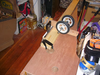
The set of wheels is just there to weigh down the other end of the guide, to make it balance better.  Actually, I will eventually build a little folding hand-truck thingie, incorporating those wheels, to help me transport this pandalon, and also for transporting my electronic pipe-organ gear (not all at the same time).


Here I've moved my reference lumber forward, having reached the end of its first position.  It will probably take me a total of four or five days to complete this long spine side cut.  Then, I'll have to do the other sides (everything except the front edge), which all add up to significantly more perimeter than the 8-foot spine side itself.  So, I'm a good bit less than half way done...


After a while, the sawing motion becomes very Zen-like, trance-inducing.  Still, I'd use a power tool and get my Zen trances some other way, given the choice!

Friday, October 4, 2013

soundboard barring, trimming the wrestplank, and squaring-up the frame perimeter

A few design and construction decisions.  I decided to put three bars under the soundboard, as you can see.  The reason, initially, was simply to make it stiffer.  Given that, I decided to copy what I've seen in some existing harpsichords, as far as the locations; I would not have dared to put bars under the bridge, otherwise.  This barring is somewhat similar to some Italian harpsichords.  The suggestion is that it leads to a brighter tone with more upper harmonics.  Which is what I want; the evolution of the piano has been away from the extremely bright tone of the harpsichord; later generations of the piano have added more and more felt to the hammers, producing a dull, muffled tone -- unless the keys are played quite hard.  The velocity-dependent tone-colour change of the modern piano is an interesting effect, but it always seems to leave me with the wrong tone at the wrong volume level: I want bright, trebly, delicate tone colour even when I play soft -- especially when I play soft, in fact.  So, my pandalon will have hard wooden hammers, not covered with felt or leather; when a more muted tone is desired, there are two stops available to muffle the tone: the moderator and the buff.  The moderator puts some kind of cloth or leather in between the hammers and the strings; so the effect is similar to having the hammers covered with the same material.  The buff presses cloth or leather up against the strings, near their ends; so the sustain duration of the string is reduced, unlike with the moderator.

Anyway; my soundboard-barring is total guesswork, slightly-informed by some things I've seen.  But I'm guessing that my motivations and approach are quite possibly very similar to those of the Original Builders, inadvertently.  Bars were surely put across soundboards first for simple structural reasons, and then adjusted and repositioned to optimize the sound, once their inevitable effect on the sound quality was noticed.

And then, there's the matter of my sound holes.  I hadn't been planning to have two, but as I began to dry-fit the parts together, I saw that the main internal diagonal brace creates an almost-complete partition of the soundbox, into two distinct regions.  So I put a hole on each side of the partition, positioned and sized by more "intuitive guesswork".

By holding down the edges of the soundboard against the frame, I can approximate the tone it will have when glued into place.  Tapping the soundboard all over its surface shows me that it is nice and "lively", and seems to have a good tone as far as bass and treble balance.  (I am no expert, however.)  I am glad to find that both sound holes seem to "do something", in that the sound changes noticeably when one or the other is covered up by my hand; they both radiate sound, for taps occurring anywhere on the surface.  These are good signs...


My "mitre guide" turns out to be the best tool for just about every occasion, anymore!  Here, it helps me trim the wrestplank ends.  Later, I have started to use it to help me "machine" the sides of the frame; progress is slower than I ever expected for these operations (I thought I'd figure out some way to use power tools), but results are accurate.


There's the trimmed wrestplank, resting in the (untrimmed) frame.  You can perhaps see from my Sharpie-markings on the wrestplank, the four-octave band of strings will leave a fair bit of width on either side, unused.  I could extend the bass and/or the treble by several notes, if I wanted to.  However, I'm not especially eager to have higher notes than what I've planned; of course I'd take more bass, but the current bass limit (E2) is derived from the case length and the need to use iron strings to work with a pickup.  Someone who didn't care about the pickup could add some deeper bass notes using brass wire.

But basically, my conception for this is 4-octave (49 notes).  I'll build some bigger, 5-octave instruments, using what I learn here; a harpsichord, and who knows, perhaps a bigger pandalon as well.  (The additional notes will mostly be in the bass, probably at least down to F1 instead of stopping at E2.)


Here I am setting up the saw-guide for trimming the frame.  Basically the whole perimeter of the frame needs to be sawed flat, to make smooth vertical faces to which I can attach the outer case walls.  This is usually done with powerful (electric) machines these days...  With the dainty little teeth on my Buck Bros. PVC pipe saw, I can chug along at, probably, 10cm per hour or so, on average.  This step, more than any of the others so far, is the one where I become quite committed to this particular frame!  No more thoughts of maybe it's too messed up and I should start over with different lumber.  Nope, as of now, I'm all in.  (Hearing that the soundbox "taps well", is probably another thing that makes me ready for "committment" with this frame.)