Tuesday, October 15, 2013

easier journey than I thought

Turns out, I think the only frame member which was far enough off vertical to require the labourious trimming process, was the spine.  So after five days of slowly sawing that timber end-to-end through its wide axis, I think I am now done with that operation, I don't need to continue on and saw all the way around the other sides, a longer distance than I have covered so far.  Phew!  It's like finding out that you don't need to backpack that next 100 mile stretch, you're already in the right place.

Keeping the existing faces of the other 2x4s, it was thus only necessary to trim the top (soundboard) and bottom plywood sheets, which I had cut slightly oversize.  I did this also with my Buck Bros. PVC saw, but without the guide, just following drawn lines.  Progress was so zippy, going through 3/16" plywood instead of the wide face of a 2x4.

Next up, I can finally start to fit the outer side lumber, i.e., the "case".  I'll use my mitre guide to make mitre cuts: finally the purpose for which it was intended!  It has been invaluable in these other, 90-degree applications, too.

I have been planning to use "glue-n-screw" to hold the outer case lumber against the frame pieces.  A straight line of black drywall screws down the center of each side: I thought they'd possibly even look somewhat decorative, slightly evocative of the inset decorations on some fancy Italian harpsichords.  But, now I'm thinking, clamps may be better.  Problem is, I don't have clamps.  Well, I have two.  I think I will need at least four more, and probably ones which can go wider than my 3" metal C-clamps.  Those proper carpenter's clamps seem to be pricey for what they are, but that's exactly what I need.  So I think I will build my own, out of 2x2s and threaded rod.  They will be a little less convenient than the real ones, I'll have to use a crescent wrench to tighten them in a somewhat tedious fashion.  But they should apply the right kind of pressure.  The Titebond II glue that I'm using should allow ample time to fit the glued lumber together, and then slowly clamp it up.

I was also planning glue-n-screw for the soundboard, and I might still do that, since the "right" way requires a dedicated shop space ("go bar" table).  Ways to construct a more-portable go-table are in play in my thoughts.  But another option is edge-molding: either glue-n-screw with the screws hidden by the molding, or perhaps the molding itself can be used to clamp down the edges of the soundboard.  The cut edges of the plywood look better than I thought they might, but still I think the overall visual effect would be better if the edges were overlapped by molding, and also if there were no screws.  Of course, part of my reason to have screws was to overturn established assumptions and draw attention to the fact that the construction methodology was quite different.  But since even I can't seem to resist the desire to have no screws showing, I can assume that others wanting to copy this design will also feel that desire: so I might as well work out how to do it in a simple manner, even though it deviates from the "minimum effort and construction complexity" principle, slightly.

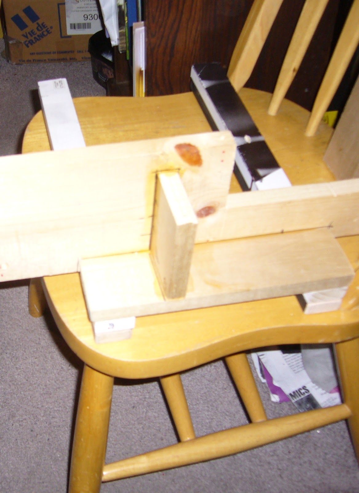
Here's my little saw-guide-and-2x4 rig, reaching the end of my five day journey through wood.  I'm glad I didn't have to do this to all the other sides!  I had developed a pretty good rhythm; about three "bouts" of 256 saw-strokes each, give or take, with a rest in between; and then it would be time to move the guide down.  I could have probably figured a pretty close estimate of the total saw strokes to make this 8-foot cut, but let's just say, must be tens of thousands.


Tuesday, October 8, 2013

a long journey through wood...

Here I go, using my mitre-guide to make a square cut, again.  I have yet to use it for mitres -- though that is coming up, once this trimming operation is finally done.  I have to make my not-very-flat 2x4s into truly flat, vertical faces, so that I can glue the outer boards directly to them.  I thought about using some kind of glue+sawdust filler compound, and attaching the boards to the non-flattened raw 2x4s, adjusting for the poor fit by filling in the cracks with compound.  But I realized, it would still be highly complicated to clamp the outer boards into the proper vertical-plane orientations, without the underlying 2x4s as a reference.  Chances of the final result looking better than crap, not so good.  Basically, my original design assumption, that I could count on the from-the-factory faces of the lumber to be straight enough without further work, has proven to be totally wrong.  This in turn causes my whole "maximum tone quality for minimum cost and effort" concept to basically fly out the window (at least the effort part).  But at least I'm still on track to end up with something that I can play, and which looks halfway decent.


The mitre-guide is clamped to a horizontal 2x4, which causes the cut to be square relative to the overall flatness of the soundboard.  As I saw my way along, cm by cm, I guide the front end of the mitre-guide with the pressure of my hand, using the edge of the flat lumber I have put on top of the soundboard, as a reference.  So the straightness of the line is "by-eye", and it may be wavy at longer distance scales, but I hope the outer lumber can be clamped to conform; and at the least, the vertical walls of the cut should be just that, vertical -- at least to within a degree or so, I'd hope.


The set of wheels is just there to weigh down the other end of the guide, to make it balance better.  Actually, I will eventually build a little folding hand-truck thingie, incorporating those wheels, to help me transport this pandalon, and also for transporting my electronic pipe-organ gear (not all at the same time).


Here I've moved my reference lumber forward, having reached the end of its first position.  It will probably take me a total of four or five days to complete this long spine side cut.  Then, I'll have to do the other sides (everything except the front edge), which all add up to significantly more perimeter than the 8-foot spine side itself.  So, I'm a good bit less than half way done...


After a while, the sawing motion becomes very Zen-like, trance-inducing.  Still, I'd use a power tool and get my Zen trances some other way, given the choice!

Friday, October 4, 2013

soundboard barring, trimming the wrestplank, and squaring-up the frame perimeter

A few design and construction decisions.  I decided to put three bars under the soundboard, as you can see.  The reason, initially, was simply to make it stiffer.  Given that, I decided to copy what I've seen in some existing harpsichords, as far as the locations; I would not have dared to put bars under the bridge, otherwise.  This barring is somewhat similar to some Italian harpsichords.  The suggestion is that it leads to a brighter tone with more upper harmonics.  Which is what I want; the evolution of the piano has been away from the extremely bright tone of the harpsichord; later generations of the piano have added more and more felt to the hammers, producing a dull, muffled tone -- unless the keys are played quite hard.  The velocity-dependent tone-colour change of the modern piano is an interesting effect, but it always seems to leave me with the wrong tone at the wrong volume level: I want bright, trebly, delicate tone colour even when I play soft -- especially when I play soft, in fact.  So, my pandalon will have hard wooden hammers, not covered with felt or leather; when a more muted tone is desired, there are two stops available to muffle the tone: the moderator and the buff.  The moderator puts some kind of cloth or leather in between the hammers and the strings; so the effect is similar to having the hammers covered with the same material.  The buff presses cloth or leather up against the strings, near their ends; so the sustain duration of the string is reduced, unlike with the moderator.

Anyway; my soundboard-barring is total guesswork, slightly-informed by some things I've seen.  But I'm guessing that my motivations and approach are quite possibly very similar to those of the Original Builders, inadvertently.  Bars were surely put across soundboards first for simple structural reasons, and then adjusted and repositioned to optimize the sound, once their inevitable effect on the sound quality was noticed.

And then, there's the matter of my sound holes.  I hadn't been planning to have two, but as I began to dry-fit the parts together, I saw that the main internal diagonal brace creates an almost-complete partition of the soundbox, into two distinct regions.  So I put a hole on each side of the partition, positioned and sized by more "intuitive guesswork".

By holding down the edges of the soundboard against the frame, I can approximate the tone it will have when glued into place.  Tapping the soundboard all over its surface shows me that it is nice and "lively", and seems to have a good tone as far as bass and treble balance.  (I am no expert, however.)  I am glad to find that both sound holes seem to "do something", in that the sound changes noticeably when one or the other is covered up by my hand; they both radiate sound, for taps occurring anywhere on the surface.  These are good signs...


My "mitre guide" turns out to be the best tool for just about every occasion, anymore!  Here, it helps me trim the wrestplank ends.  Later, I have started to use it to help me "machine" the sides of the frame; progress is slower than I ever expected for these operations (I thought I'd figure out some way to use power tools), but results are accurate.


There's the trimmed wrestplank, resting in the (untrimmed) frame.  You can perhaps see from my Sharpie-markings on the wrestplank, the four-octave band of strings will leave a fair bit of width on either side, unused.  I could extend the bass and/or the treble by several notes, if I wanted to.  However, I'm not especially eager to have higher notes than what I've planned; of course I'd take more bass, but the current bass limit (E2) is derived from the case length and the need to use iron strings to work with a pickup.  Someone who didn't care about the pickup could add some deeper bass notes using brass wire.

But basically, my conception for this is 4-octave (49 notes).  I'll build some bigger, 5-octave instruments, using what I learn here; a harpsichord, and who knows, perhaps a bigger pandalon as well.  (The additional notes will mostly be in the bass, probably at least down to F1 instead of stopping at E2.)


Here I am setting up the saw-guide for trimming the frame.  Basically the whole perimeter of the frame needs to be sawed flat, to make smooth vertical faces to which I can attach the outer case walls.  This is usually done with powerful (electric) machines these days...  With the dainty little teeth on my Buck Bros. PVC pipe saw, I can chug along at, probably, 10cm per hour or so, on average.  This step, more than any of the others so far, is the one where I become quite committed to this particular frame!  No more thoughts of maybe it's too messed up and I should start over with different lumber.  Nope, as of now, I'm all in.  (Hearing that the soundbox "taps well", is probably another thing that makes me ready for "committment" with this frame.)


Thursday, September 26, 2013

gluing the back on, and damper design

So, here I'm putting the back plywood panel on; which covers the soundbox, but not the keyboard area.

The plywood is only 3/16" thick.  This is a big part of my concept, "beams and stressed fabric", like an (oldschool) airplane wing.  The plywood won't contribute any twist-resistance or compression-resistance on its own, but by enclosing the frame "triangles", I hope the resulting boxes will be greatly strengthened against critical deformation modes, by the good tension-resistance of the plywood.  The soundboard will be the same thickness and material, attached on the other side.  Normally the back would probably be thicker than this, but I both wanted to fully validate the "stressed fabric" concept, and to end up with as light as possible of an instrument, as a practical matter (this prototype, assuming it works, will become my own working instrument which I may end up transporting and carrying around quite a bit).

The back is glued-and-screwed, my usual procedure to avoid the need for (explicit) clamps...

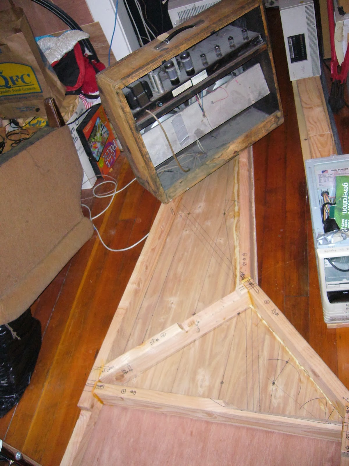
...and then I've weighed down the tail especially firmly to flatten out the twist as mentioned before.  You can see my tube guitar amp (much better suited to this use than a solid-state amp of equal power!), and beyond it, just the corner of the Sun monitor, a heavy beast with a nice big flat square base, perfect for the job.  I'll still need to machine the outer faces of the timbers, somehow, to make them sufficiently flat and vertical, but at least the frame will be in one plane.

I will let the frame rest in this weighted condition for a number of days: not only to let the glue dry, but also to at least get a start on drying out the moisture from my "wet pack" experiment on the spine piece.  Which was pretty ill-advised, I now think, but the "data" from observing the reaction of the wood is probably worth the damage in the long term!


Meanwhile, I've been continuing notebook-work on the action design.  I think I will need a deeper floor under the action, than the rest of the instrument (i.e., the soundbox).  This works out, because the side-lumber (1x6) that I have are too short to reach the whole length on the long (spine) side, anyway: so there was going to be a seam regardless.  Now, this vertical seam will occur at the end of the soundboard, as the lumber changes from 1x6 to, probably, 1x8 (but possibly trimmed down).  The line of the top will remain the same, but the bottom will "bulge" downwards a bit, under the wrestplank and keyboard: perhaps by another inch.  I don't think it will hurt the aesthetics any; indeed, visually I think it'll look good to have a little more "mass" at the keyboard end, balancing against the general long-and-thin profile.

I've been refining the design of the dampers.  I am back to dampers-from-underneath, after briefly considering dampers-from-above.  The dampers will have (mild) spring tension holding them against the strings, and the keylever will pull them away under tension; i.e., the spring force will be added to the playing force of the key, not subtracted as in some of my past iterations of this design.  I had been planning a set of secondary levers, with all the attendant guides and whatnot, to transfer the keylever motion to the dampers.  The issue is that I want the dampers to move only a small distance, whereas the end of the keylever with the striker, right next to the damper, moves quite a lot, probably about 3x the player's keystroke distance.  So even if it was to be dampers-from-above, I wouldn't want to use the simple approach of having the keylever directly lift the damper: that would be too much motion, needlessly fast, too much inertia, and too much sensitivity to friction in the damper guides.  So levers would have let me select a driving point on the keylever, closer to the pivot center, with less motion and greater leverage to overcome friction.  But, even very lightweight levers would (quite possibly) have problems with resonance and/or lag, especially during rapid repeats, which could lead to a surely-undesirable jerk effect (high third derivative).

So now, latest version, I plan to simply use nylon monofilament to transfer the motion, with no secondary levers.  The damper will be held against the string as mentioned, under spring force.  The monofilament line will run downwards from the bottom corner of the damper wire, to a "pulley" on the floor of the action assembly, then horizontally across to another "pulley" on the floor,  located closer to the key pivot-point, and then up to the keylever.  The position of the second "pulley" can be shifted forwards or back arbitrarily, to select the leverage point anywhere along the keylever.  I'm thinking probably 1:1 with the keystroke, if the striker is 3:1.  But maybe even reduced from that, like 0.5:1.  I am planning a very shallow key-dip, maybe about 1/4".  The damper motion wants to be small; but the issues with making it too small are that there must be enough motion to reliably get the (compressible and fuzzy) felt fully out of the way of the strings, especially in the bass where the vibrations are larger; and also, there must be enough *more* motion than the minimum, so that the transition to damper-open happens well above the bottom of the keystroke (ideally about halfway, I think).  This is all to minimize the amount of extra force or friction perceptible to the player when the dampers are operational, vis a vis when the sustain pedal is down, while at the same time allowing a reasonably robust spring force on the damper itself so that it will damp quickly and effectively -- especially because I have made the damper and striker positions so close to the nut, aiming for a bright and nasal voice.

Continuing the saga of the monofilament.  After passing through a hole in the side of the keylever, which defines the leverage point, the monofilament does not terminate right there, but rather continues all the way forward to the player's end of the keylever.  There, it terminates at an eyelet which behaves like the tuning pins on the wrestplank: by turning the eyelet, the length of the monofilament can be changed, which adjusts the rest position of the damper.  (This can be used both to adjust the dampers for consistent action, and to compensate for any stretch in the monofilament.)

The sustain pedal (and handstop) operates by pressing against the damper springs independently of the monofilaments; thus, the lines go slack when the pedal is active.  Care must be taken that the lines are arranged so they cannot snag or interact with each other in any way, or otherwise get off their intended tracks, when they go slack thus.  Which brings up the "pulleys".  I've been putting quotes around the word, because I think that instead of actual pulleys with moving parts, I can probably just use continuous, shiny, circular-section rails (i.e., small pipes), one each to effect all of the "pulley 1"s and the "pulley 2"s.  The monofilament lines will simply slip around these shiny tubes, making a right angle at each one, hopefully moving with low friction.

Wednesday, September 25, 2013

gluing up the frame

Well, now I think I understand all the things I have done wrong so far, in building this frame.  The *next* one, I'll be able to do a much better job on!  But what about this one?  The big problem is that I made the angled cuts on the ends, before the lumber was fully dry.  As it dried, the lumber changed shape slightly, and so the precision of my cuts suffered.  I felt some time-pressure due to only having access to the chop-saw for a limited time, and this in itself was probably a problem.  This stuff just takes time.  The trade-off for saving money by buying cheap, non-kiln-dried framing lumber and trying to use it for a musical instrument, is that it takes an extra six months for the lumber to be ready for use.  During the drying period, the lumber should be restrained to keep it flat and straight.  I made some efforts in this direction, but clearly not enough; I think I will need to build a special restraining frame for drying lumber in the future.  My longest piece, the spine piece, the full 8' long, developed a pronounced twist: maybe as bad as 10 degrees or so.  Well, rather than throw away all this time and money investment, I will try to make it work anyway, partially as a way to develop techniques for dealing with these problems; and even if it's not perfect, I really want to get something built up to the point that I can string it and verify whether my basic design can withstand the tension and produce good tone.

So here's my attempt to fix the twist in the spine-piece (the long one on the left).  I have been gluing the frame members together one by one.  First, I attached the horizontal member, not visible in this first photo, at right angle to the spine, which locked the front end of the spine piece into its correct orientation, i.e., at right angle to the plywood bottom.  The spine member twists CCW, going towards the tail end, so by the tail, its top edge is leaning outwards by the 10 degrees or whatever.  Here, I have attached the short crosspiece to the spine at the tail end, and then the longer of the two "bentside" segments, on the right side.  I connected these joints flat together, directly as the original cuts dictated -- as opposed to "fixing" (compensating for) the spine twist at the first joint in the tail.  Thus, the twisted spine causes the bentside member to angle upward, rather than lying flat on the plywood.  As you can see, I propped up this member during gluing, so that it would retain the "wrong", twisted position.  This now gives me a big lever (assuming the joints hold -- which is also under-test in this operation), which can be used to force the spine to twist back.  (Maybe.)


Next I glued all the other joints, of the smaller triangle close to the keyboard.  In this photo the final joint of the long bentside piece to the intersection in the middle of the bentside, has not been made yet.  You can see that I have wrapped an area of the spine timber with plastic, and inside I have paper towels saturated with water.  I will keep this wrap on for a few days or a week as I finish the gluing and put the spine under torsion, hoping that extra humidity will help bend the wood and get it "used" to its new orientation.  I don't know how wise this is, the opposing concern is that I don't really want to return the wood to its fully-wet condition like when I bought it (or worse), because drying from that was the cause of all the problems in the first place.  But anyway, we'll see, it's all just an experiment.


As the wood dimensions changed during drying, you can see how far off this formerly tight joint ended up!  As I have closed up all the other joints already, the error effectively is all transferred to this one.  I fit the two pieces of basswood, well-saturated with Titebond II, with the originally-intended single 2+1/2" #8 screw going through the whole "sandwich".  Hopefully this joint, primarily under compression and shear, will be strong enough.  Pretty, it ain't!  This will be fully enclosed and hidden -- but I still wouldn't sell this to a customer.  This is the life of a prototype...


It is exciting to see the frame, now able to stand as a solid unit by itself, rather than just the pieces laid out.


Completing the bentside 3-way joint has put considerable twist on the spine, and the twist error is reduced partially.  But still, left unrestrained, the short tail piece (naturally) does not lie flat, so there is more counter-twist to be obtained.  I plan to attach the bottom plywood, glued-and-screwed, and then weight the tail down flat while it dries.  (I have a lovely Sun Microsystems 19" monochrome CRT monitor that volunteers for this task.)  And by then I will have removed the wet-pack.  Then, I'll let the lumber, as well as the glue, dry out for a good number of days before removing the weight.  I'll work on other stuff like the soundboard while this is going on.  And... we'll just see how it all works out.

Even once the tail frame members are all flat, there will still be some twist-error; I guess I should have added a little overcompensation or "leading" into the spine-tail joint, so that it would all settle out to the right amount of twist.  But I didn't have the confidence to guess right on that, so I went with the straight, best-fitting position of the joint, i.e., as originally cut, knowing that with no overshoot I would not be able to completely iron out the spine twist.  It helps a lot; but, what about the remaining error?  And in general, the outer faces of these frame members are pretty rough and warpy.  The issue is, I want to attach the outer layer of nicer-looking lumber, my poplar 1x6s, by gluing them flat to the frame timbers.  Thus, they will contribute significantly to the top-to-bottom flex resistance of the frame, as well as adding a smaller amount of sideways stiffness.  But the twisted spine piece especially, is not suitable for such attachment, and probably other frame members would be problematic as well.  Any slight deviation from the vertical plane will mess up my beveled joints, and will just look crappy.

So the obvious solution is to plane (or otherwise machine) the sides.  That's what "real" woodworkers do, as a matter of course, in building stuff like this.  I am attempting to use the existing faces of the lumber, as much as possible, to avoid the need for "real" woodworking tools and a shop.  But this means compensating for and anticipating this reduced precision, through the design.  In this case, though, especially with the twisted spine piece, I do need to find a way to machine the wood.  Possibilities include, building a special saw-guide (or modifying/adding to the one I have) to trim a vertical plane; or maybe, I have a handheld vibrating power sander, which I could maybe build some kind of carriage for, to hold it in a vertical orientation.  Stay tuned...

Not necessarily as an alternative to machining the wood, but perhaps to complement it, in certain places where I inevitably or by-design have space in a joint, a gap, I think I'm going to have to develop a Titebond-and-sawdust mixture.  I hoped originally that, at least with small gaps, I could count on the glue to fill these.  The Elmer's type glues tend to have this filling ability; though I had noticed that their "new" wood glue formulation, which seems to be similar to Titebond II, was significantly different in consistency and behaviour, and did not seem to fill as well.  In any case, Titebond II itself has virtually no gap-filling capability.  Partially, this is perhaps simply because the glue in its liquid form is not very viscous, and can't be made to even "seem" like it's going to fill many cracks.  But even if it appears to be filling a void in the short term, I find that it usually wicks away into the wood and causes voids to be open, by the time it dries.  They're not kidding when they say that joints need to fit well and be well-clamped, for this glue to work.  The low viscosity, and/or high "wickability" (perhaps this is the same property?), clearly contribute to the strong bond capability of this glue.  I have read that it was standard practice for ancient instrument builders to mix (hide) glue and sawdust, to make a filling compound.  I think I will need to do the same, for some areas in this project.

Also: in several places in the design of my action mechanism, I rely on a bead of viscous glue to lock-in the heads of nails, fitting through holes in a rail.  This is sort of one of my design idioms.  But Titebond II will clearly not work in this application, any more than superglue -- which I tried in my dulce-melos zither project.  I guess I will still need to "stock" Elmer's Glue for these applications.  (I have this other silicone glue, which I used to attach the sharp tops in the pedalboard project, but I was not happy with it, it never seems to fully dry; it would be better as a sealant perhaps, than as a glue, at least by my definition of "glue".)


Tuesday, September 17, 2013

more carving, and issues with the frame design

Since last time, I've done a few additional bits of machining to the main timbers.
Also, however, just by laying out the frame pieces and thinking about the issues, I've realized that the frame as it stands will probably not work: at least one additional piece of lumber will be needed.

I used my "mitre cut guide" for the first time in earnest, and already, I'm not using it according to the "instructions".  It turns out to be my best-available way to make straight 90-degree cuts, too.  I clamped the timbers in question to the nice, flat, square faces of the prefinished 1x3 comprising the inner upright of the guide.  Thus, I obtained nice flat surfaces for the wrestplank to fit into, in the frame.
I wasn't planning to use the guide in this way (particularly the way I made the long cuts), but it worked adequately.  Glad I used the prefinished 1x3s and not regular 1x3s in those positions!


A carve-out is needed on the horizontal timber, timber 6, for the treble end of the soundboard. Like the other soundboard carve-out, this cut does not need to be precise; my little hand-saw with the "shark teeth" did the job.


Also, I drilled the four perimeter mounting holes for the wrestplank (but not, yet, all the inner holes for the tuners (98) and other items; I will lay these out after the frame is assembled and finished, so that the tuning pegs will contact bare unfinished wood).

I think I have a design problem with the frame, at the joint between the cheek and "bentside".  In my original design, the plywood bottom was to have extended under the keyboard as a single piece, and this is the impression conveyed when I lay out the frame timbers upon the sheets of plywood as above, because the plywood pieces are not trimmed to their to final shapes yet.  Actually, the bottom plywood will more or less mirror the soundboard in outline, extending only to the horizontal "belly rail".  The keyboard will be removable from the bottom, a necessity given the design of my dulce-melos action.  There will probably be a separate removable plywood floor to which the keyboard rails are attached; or there may be no floor at all, just an open frame primarily composed of the keyboard rails themselves.  Either way, no structural rigidity can be counted on from this area, the instrument must be fully stable under tension with or without the keyboard present (indeed, I don't plan to even start building the keyboard until after the frame is already built, finished, and under tension).  The end of the long spine timber on the left, and the parallel short cheek timber on the right, need to project like tines of a fork and support the wrestplank, with all its tension and twisting force.  The spine side has innate resistance to twisting by virtue of being one long piece of wood, but the short cheek piece is in a poor leverage situation.

Given the lack of "floor", the cheek frame piece appears to be insufficiently supported; the wrestplank will of course exert a large twisting force which the closely-spaced joints to the other timbers don't have much chance of opposing.  There will be additional strength contributed by the outer case, but that will mostly be effective for preventing flex in long members such as the spine piece; the case won't contribute the type of strength that is needed here.

I think I want some kind of diagonal brace underneath the level of the keyboard, and under the floor of the sound cavity.  I hope to still keep the height of the case sides the same, my relatively narrow 1x6 lumber (not 6 inches of course); but there is a progressive shift to lower sides, less on top.  Originally the sides would have been one plywood thickness lower than the bottom face of the frame 2x4s.

I suppose, in a larger-scale redesign, one might try to make the cheek piece longer, and make the joints to the other timbers more separated, so that more rigidity is imparted to the cheek.  Even a small amount might help the leverage.  However, I think the cheek still would need a brace to give it "box strength".  Frankly, the plywood floor, even reinforced by the keyboard rails, would not be enough to give the needed strength even if it were permanently attached.  Its removal in this design just helped alert me to the issue.

Just shows how much the entire design is in-flux.  I try to avoid starting again entirely from-scratch, but it can happen in projects like this.  All I know is the result that I need to see, and to hear; how to get there, I make up from moment to moment!


Thursday, September 12, 2013

a slight tangent: building the precision saw-guide

As my lumber seasons, and as I progressively refine my plans for how to fit the final instrument together, all the while feeling thankful that I have not charged ahead with the construction yet, one of the sub-projects which has come to the fore is to build a saw-guide.  This is to allow me to make crosscuts through wide planks of lumber, at arbitrary angles.  Initially, I need it to cut the lumber for the case of the pandalon.  The inner frame of the instrument is made of 2x4s, but then there is an outer shell of 1x6s, adding a little more stiffness and defining the final top-to-bottom width of the case: still pretty low-profile.  The case lumber, like the 2x4s, needs to be cut with assorted mitred angles, so that it all glues together as symmetrical end-grain joints.  The power chop-saw I used to cut the angles on the 2x4s, is not able to handle wider lumber; and plus, I want to cut these by-hand, although I'd consider a circular power-saw with smaller teeth and maybe turning slower, if I had such a thing.

Considering future plans as well, as long as I'm building such a guide, I wanted it to be able to handle at least 8" wide lumber.  So-called mitre saws, though they have good teeth for fine cutting, usually have reinforced back edges to their blades, so that the maximum cut depth has to be less than the width of the blade, i.e., 2 or 3 inches at best.

All the hand saws at Home Depot have these wicked-looking long shark teeth nowadays.  They look like they'd be great for ripping through rough-hewn timbers and tree branches really fast, but I don't trust them to make a fine cut: I just don't see how it could even work.  Maybe I should give them a chance.  But instead, I picked up a nice hand saw intended for cutting PVC pipe: it has nice small teeth, and a narrow cut-width (whatever that's called).  I could never cut even a vaguely straight line at a desired plane by-eye with a saw like this, I've embarrassed myself every time I've tried.  But I hoped that with the guide, I could get better results -- and as you can see, I certainly did.


The 1x3s comprising the guide itself are held apart by the thickness of #6 metal washers.  Everything is held together with sheetrock screws to clamp it down, but then all joints are glued with Titebond II.  (My first time experimenting with this glue, vis a vis the "new formula" Elmer's wood glue; I'm planning to use Titebond II extensively to put the pandalon together, and using it here did not show up any difficulties with that plan.)


Now that's the kind of result I'm talking about!  It may seem trivial to those experienced in woodwork, but to me, these precise cuts are so much better than almost any other cuts I've made in wood, in all my years of puttering around with it, that I'm very excited.  I knew results like this were necessary to build what I'm planning to build, but to see it for the first time concretely, greatly improves my confidence in my overall instrument-building ambitions.  The right tool really helps.